Function: Device
Efficient device management
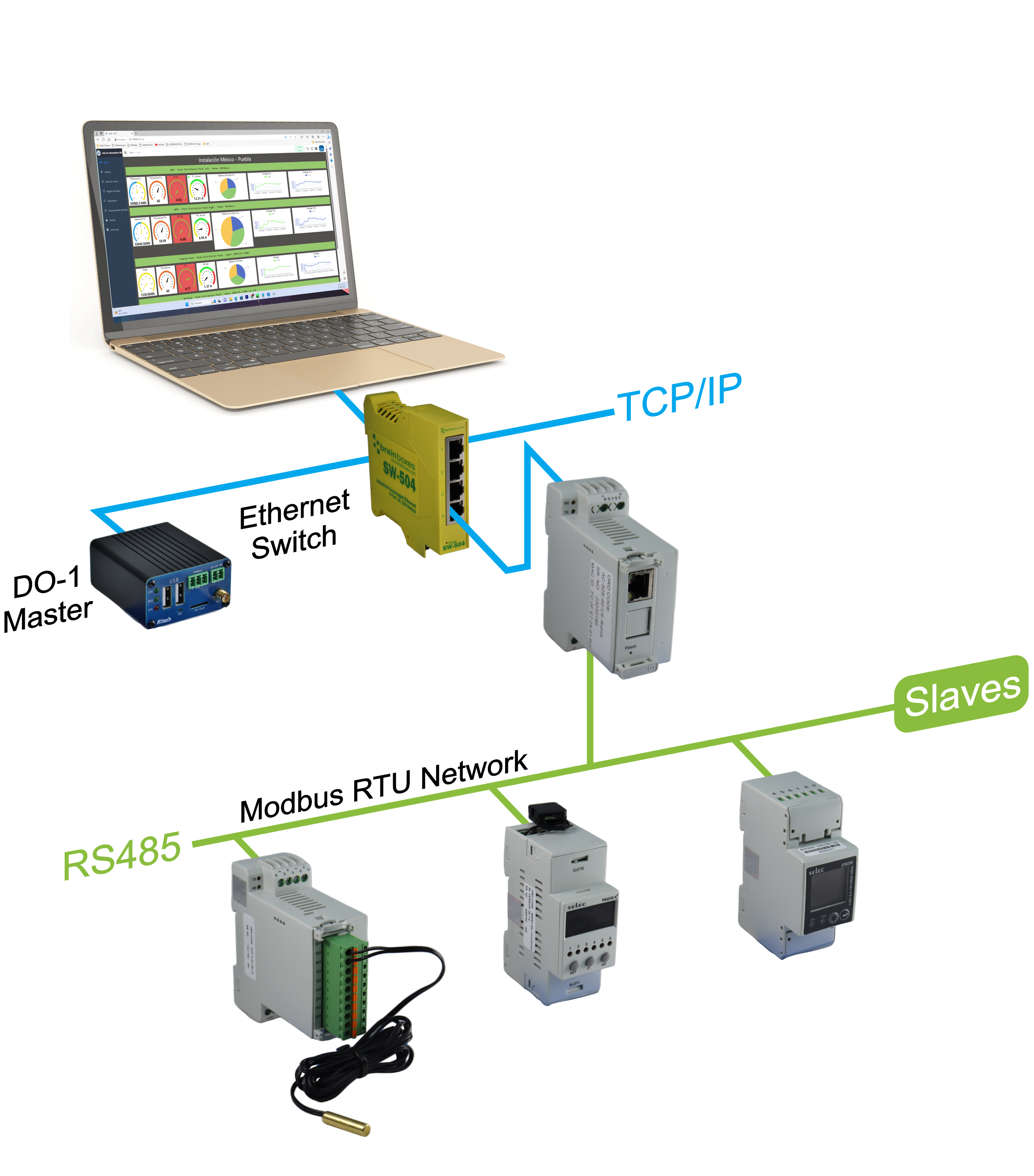
This chapter explains the Device function on the DO-1 user interface, where you will find all the necessary information about Modbus RTU , the creation of Modbus TCPs , the template library, and the registration of connected devices in the system.
Overview:
- Modbus Options: RTU and TCP
- Template Library - Specifications for the connected Modbus devices
- Device Settings: Connection of the connected devices to Modbus RTU / TCP
Modbus Options: RTU and TCP
The data for the Internal Modbus RTU is displayed under the Modbus Options menu item and can be partially customized.
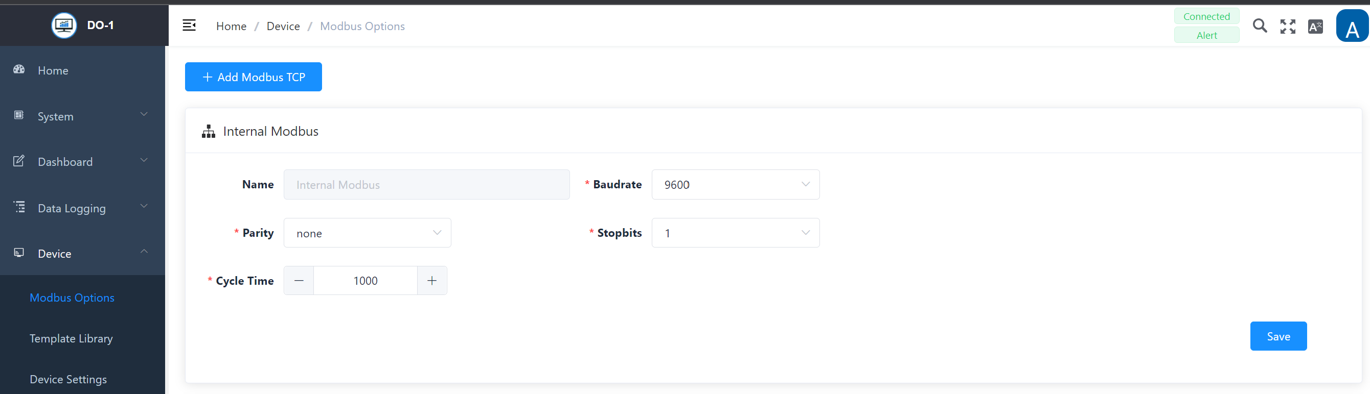
The name of the internal Modbus RTU and its settings are already stored.
Internal Modbus RTU - Settings
| Field | Description |
|---|---|
| Name | Interner Modbus – not modifiable! |
| Baud rate * | Determining the baud rate, use the drop-down functionality to select the right rate. IMPORTANT! It should be noted that all devices need to be operated in the same way. |
| Parity * | Definition of the network parities: none, even, or odd. |
| Stop Bits | Select 1 or 2 |
| Cycle Time | Specification of the time limit for the duration of a cycle. |
Note: All fields marked with * are mandatory.
Click on Save to update the details.
Add Modbus TCP
If data acquisition devices are connected to the Local Area Network (LAN) but not directly to the DO-1, a separate Modbus TCP must be created.
Click on Add Modbus TCP to open an input mask in which the settings for Modbus TCP can be entered:
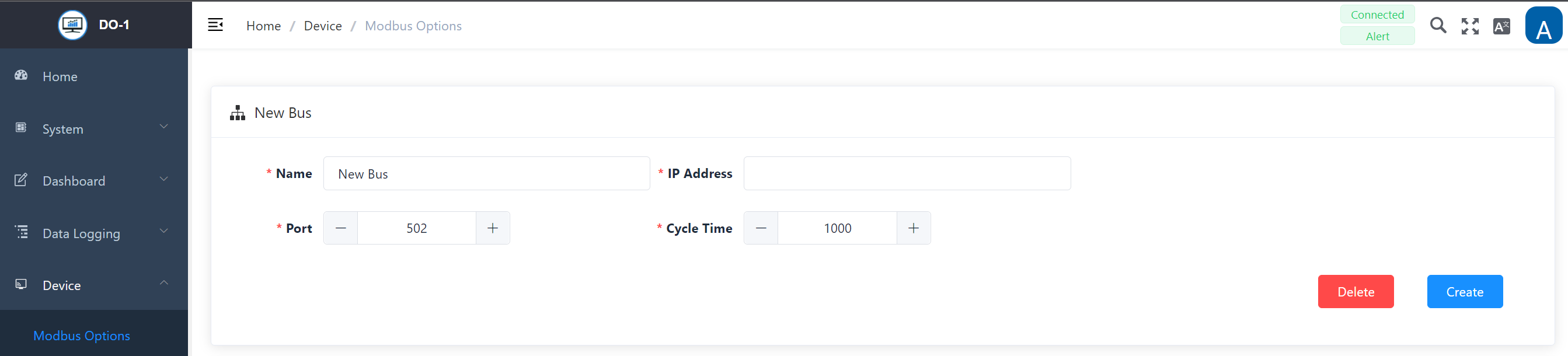
New Bus - Modbus TCP
| Field | Description |
|---|---|
| Name * | Specifying the bus |
| IP-Address * | Enter the corresponding IP address of the connected Modbus TCP device |
| Port * | Enter the port information of the connected Modbus TCP device |
| Cycle Time * | Specification of the time limit for the duration of a cycle |
Note: All fields marked with * are mandatory.
The following actions are available for the entries:
| Action | Description |
|---|---|
| Create | Creates the entries in the system. |
| Delete | Removes the entry from the system. (A warning notice must also be confirmed) IMPORTANT! If devices are already assigned to the created Modbus TCP, the entry cannot be deleted. To do this, the corresponding devices must first be removed from the Modbus TCP in the Device settings menu item. When deleting, a warning notice appears which must be confirmed. The deletion process is final and cannot be undone. |
Template Library - Specifications for the connected Modbus devices
Clicking on Template Library opens the main overview page of the library. The necessary device templates including their registers are created here so that they can be assigned to the connected devices accordingly.
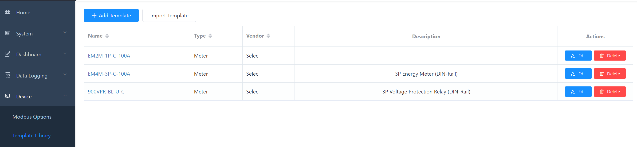
You can choose from a variety of device templates and there is also the option of importing device templates using a further function.
The following actions are available for existing/created templates:
| Action | Description |
|---|---|
| Edit | Opens the data entry for editing the details. |
| Delete | Removes the template from the system. (A warning notice must also be confirmed) |
Add Device Template
In order to be able to select information about connected devices, the corresponding information must first be stored in the system. If the device is not yet included in the existing template library, a new device template must be created.
Click on Add template to display the following entry mask:
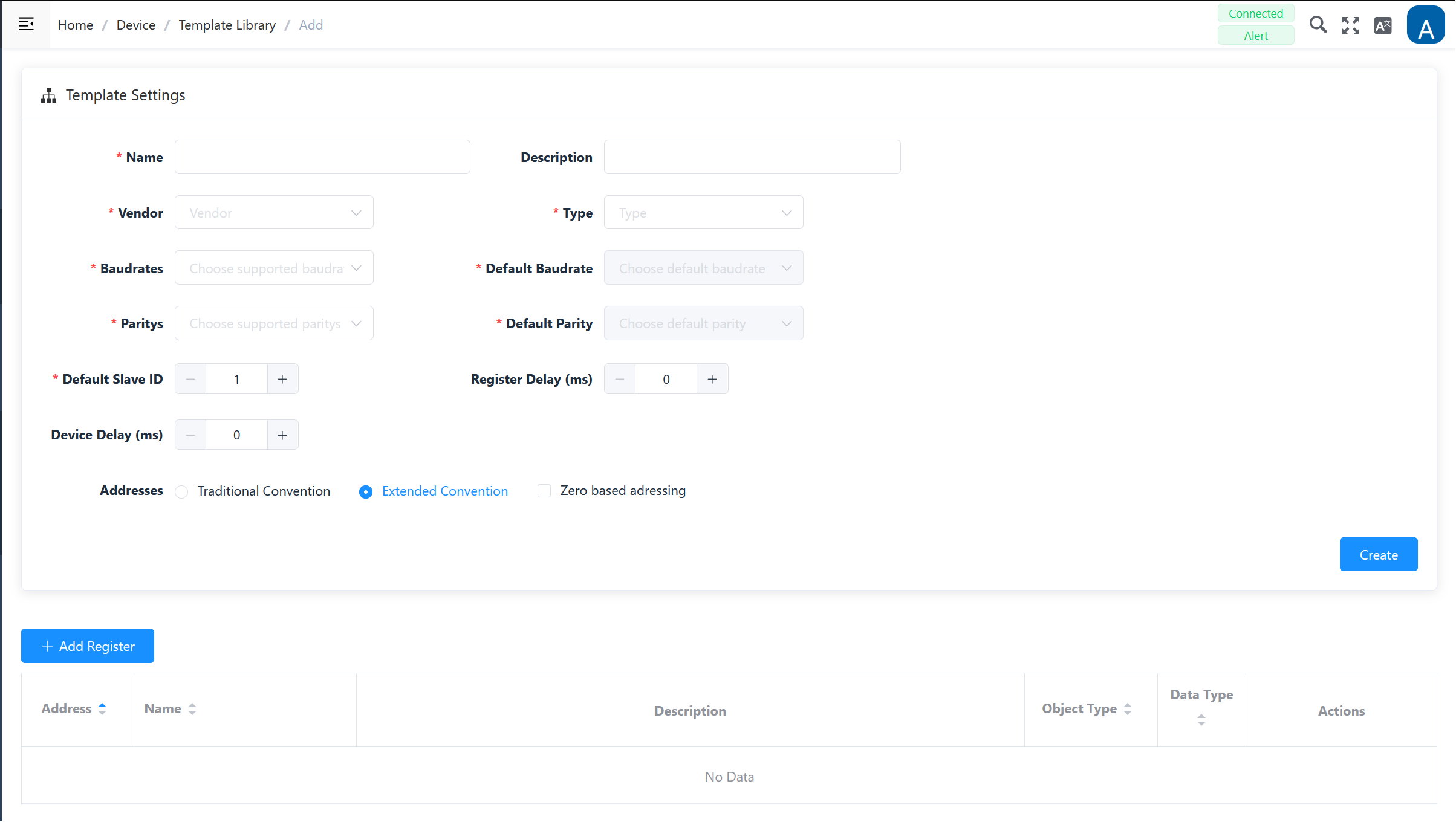
Add template - Settings
| Field | Description |
|---|---|
| Name * | Enter the name of the device template |
| Description | Any description can be added here, including a more detailed description of the device. |
| Vendor * | Input/selection of the device manufacturer (e.g. Selec, …) |
| Type * | Input/selection of the device type (e.g. meter, sensor, PLC, I/O module) |
| Baud rate * | Selection of all supported baud rates (e.g. 9600, 19200, etc.) |
| Default Baud rate * | After selecting the supported baud rates, select the standard baud rate here, which is specified in the data sheet. |
| Parity * | Selection of parity: none, even, odd. |
| Default Parity * | After selecting the supported parity, select the standard parity here, which is specified in the data sheet. |
| Default Slave-ID * | Refer to the data sheet of the device for the default setting. |
| Register Delay | Refer to the data sheet of the device for the setting. |
| **Device Delay ** | Refer to the data sheet of the device for the setting. |
| Addresses | Definition of addressing: traditional convention, extended convention, addressing on a zero basis. |
Note: All fields marked with * are mandatory.
By clicking on Create, the entries are saved and the template is created and is now available for further editing in the list view of the main page.
In the lower half, the register entries are made, which can also be found in the manufacturer’s instructions. Click on Add register to open a small window with the corresponding entry mask.
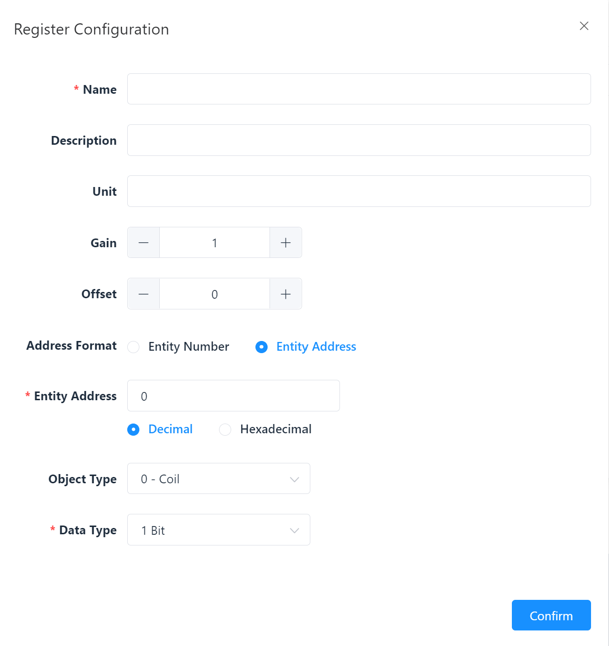
Register Configuration - Settings
| Field | Description |
|---|---|
| Name * | Assignment of the register name |
| Description | Any description can be added here, including more detailed information on the register. |
| Address Format | Selection of whether the register number or the register address of the unit is used. |
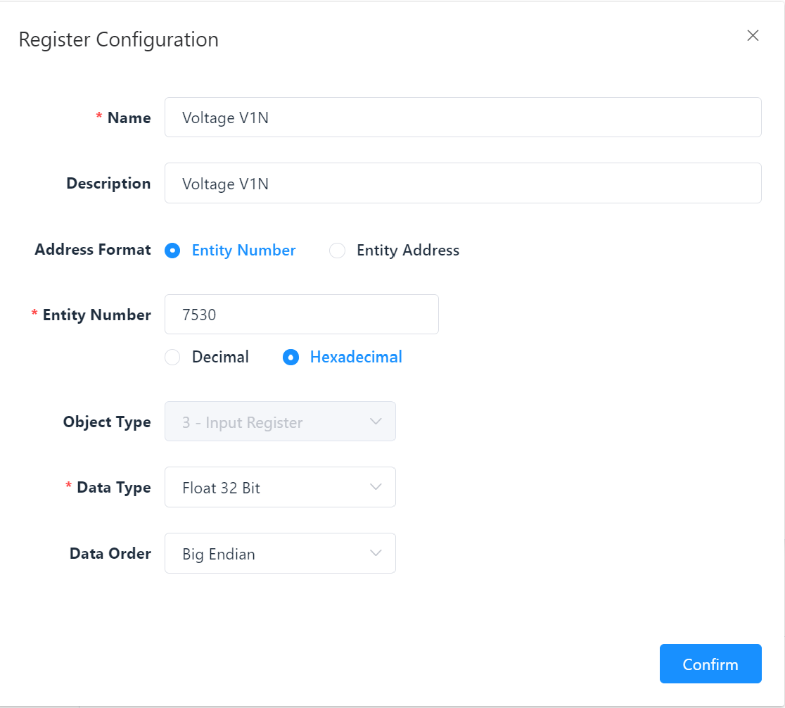
| Entity Number * | Field appears when the “Unit number” format is selected; enter the corresponding number, decimal or hexadecimal. |
| Entity Address | Field appears when the “Unit address” format is selected; enter the corresponding address, also numeric, decimal or hexadecimal. |
| Object Type | Selection only possible with previous format selection “Unit number”; 0-Coil, 1-Discrete Input, 3-Input Register, 4-Holding Register. |
| Data Type * | Definition of the bits, depending on the previous selection of the object type, the corresponding bit selection is available here. |
| Data Order | Appears only if the “Unit address” format is selected; selection options: Little Endian, Big Endian, Little Endian Reversed, Big Endian Reversed. |
Note: All fields marked with * are mandatory.
Two examples of possible register entries:
- Entity Number
- Entity Address
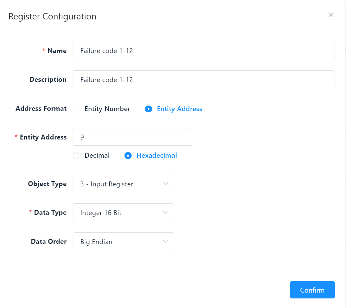
Once all the details have been entered, the respective register is saved by clicking on Confirm. After registers have been created, they are included in the register list of the corresponding template.
The following actions are available for entered registers:
| Action | Description |
|---|---|
| Edit | Opens the data entry for editing the details. |
| Delete | Removes the register from the system. (A warning notice must also be confirmed) IMPORTANT! This process must be repeated for all required sensors and measured value recording devices; otherwise, errors or incorrect value determinations may occur. |
Import Template
If device templates are available externally, they can be uploaded separately. Proceed as follows:
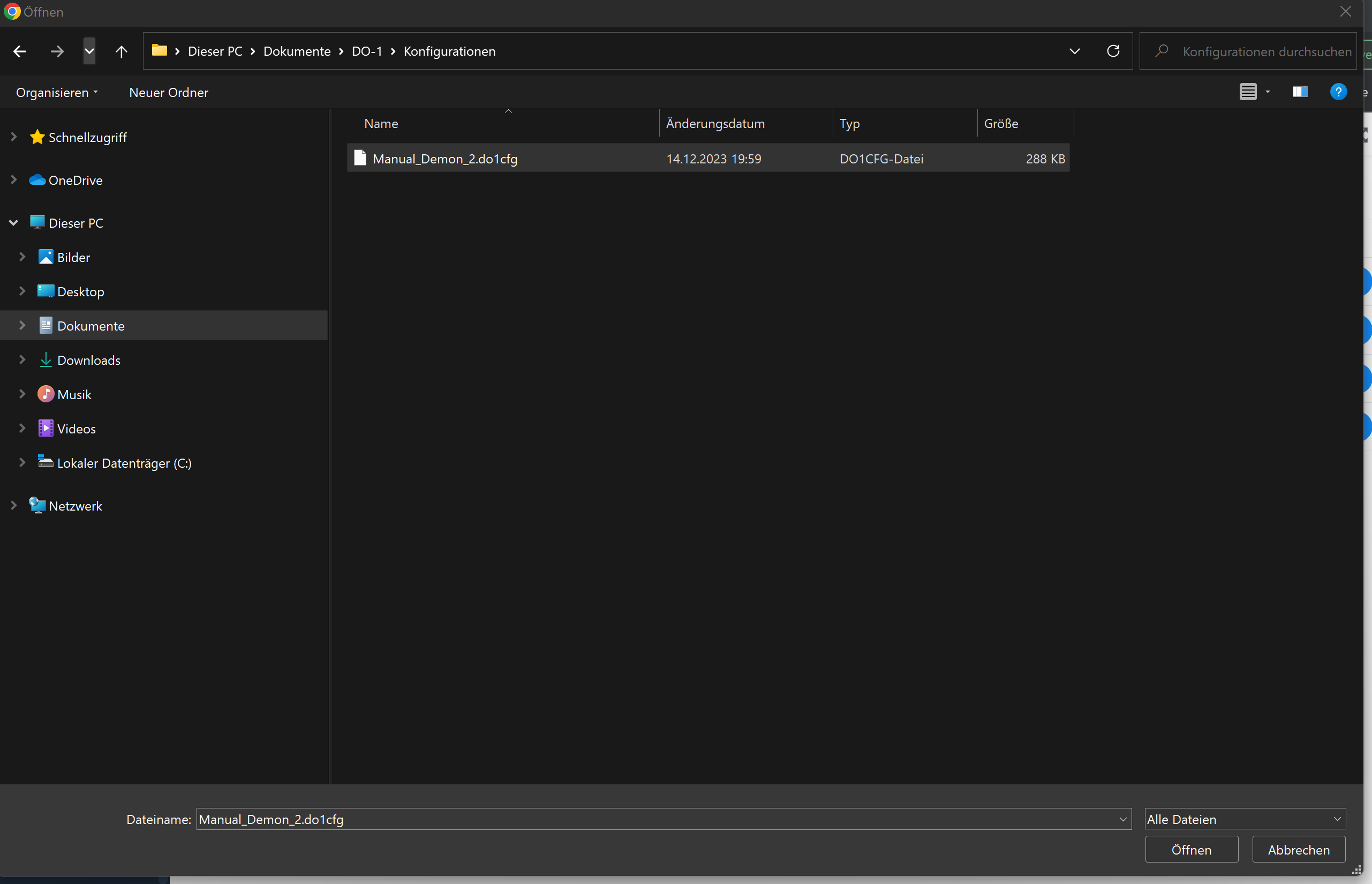
- Click on the Import template button.
- The Explorer window of the computer opens.
- Select the corresponding file from the folder or area of your own computer.
- Click on Open at the bottom right – the template is now stored in the library.
Device Settings: Connection of the connected devices to Modbus RTU / TCP
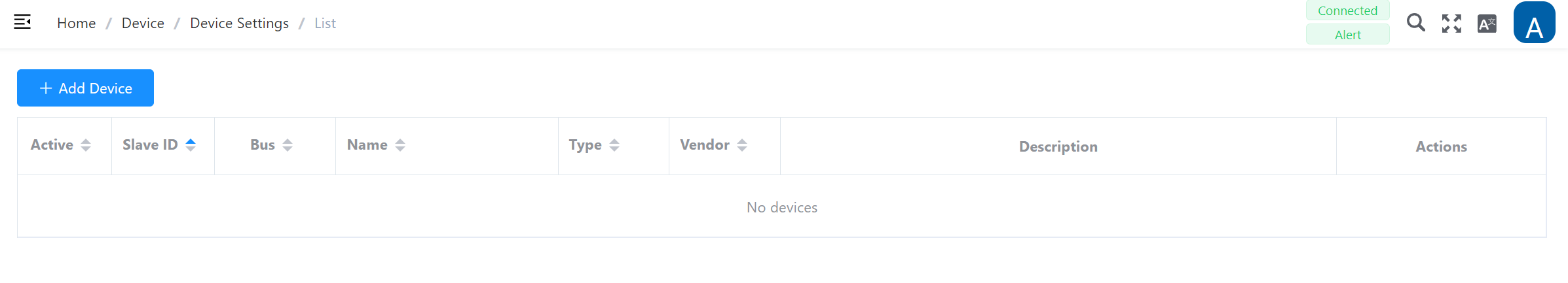
A click on Device Settings opens the main overview page. All information about the connected devices must be stored here. Initially, the list view on the main page does not yet contain any entries.
Additional Function: Active
This function can be used to deactivate or reactivate stored devices in the DO-1. To do this, operate the slider with a mouseclick.
Add Device
If a device has been connected to the Modbus RTU or TCP, the device must be created in the system so that the corresponding data storage can be configured via the DO-1. The details of the device and its register must already be available in the template library before the device can finally be created under this function.
Clicking on Add device opens the following input screen:
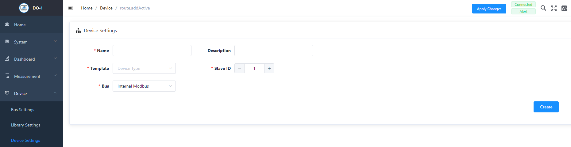
Add Device - Settings
| Field | Description |
|---|---|
| Name * | Individual; Assigning a device name |
| Description | Optional - Any description can be added here, including more detailed information about the device. |
| Template * | Selection of the template with all relevant, necessary information on the device, where the corresponding registers are also stored. |
| Slave ID * | Specification of the numerical identifier in the network that is assigned to the device. |
| Bus * | Selection of the Modbus to which the device is connected. |
Note: All fields marked with * are mandatory.
To save the entries, click on Create.
The following actions are available for created devices:
| Action | Description |
|---|---|
| Edit | Opens the data entry for editing the details. |
| Delete | Removes the device from the system. (A warning notice must also be confirmed) |
The registers saved in the device template must then be selected. Two further fields appear on the right-hand side. The “Available” list contains all the registers saved in the template.
Selecting Active Registers
To select the active registers, proceed as follows:
- Select the relevant tabs from the Available (1) list by clicking on them. It is also possible to select all available tabs by ticking the box in front of Available.
- Use the assignment function (2) (click on the arrow button) to transfer the registers to Selected (3).
- The selected registers then appear in a list view below the input screen.
- Click on Save to secure the selection. This also works in reverse for the Selected box to remove the tabs from the selection.
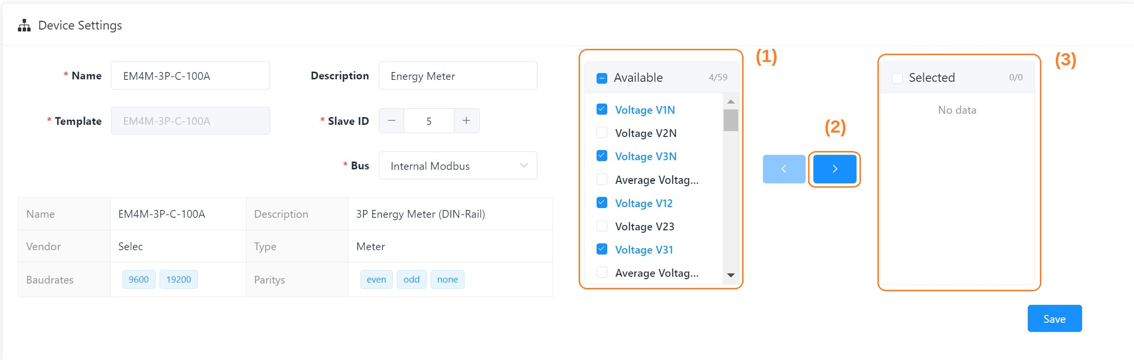
Here is an example that shows a complete device entry for a Selec Meter:
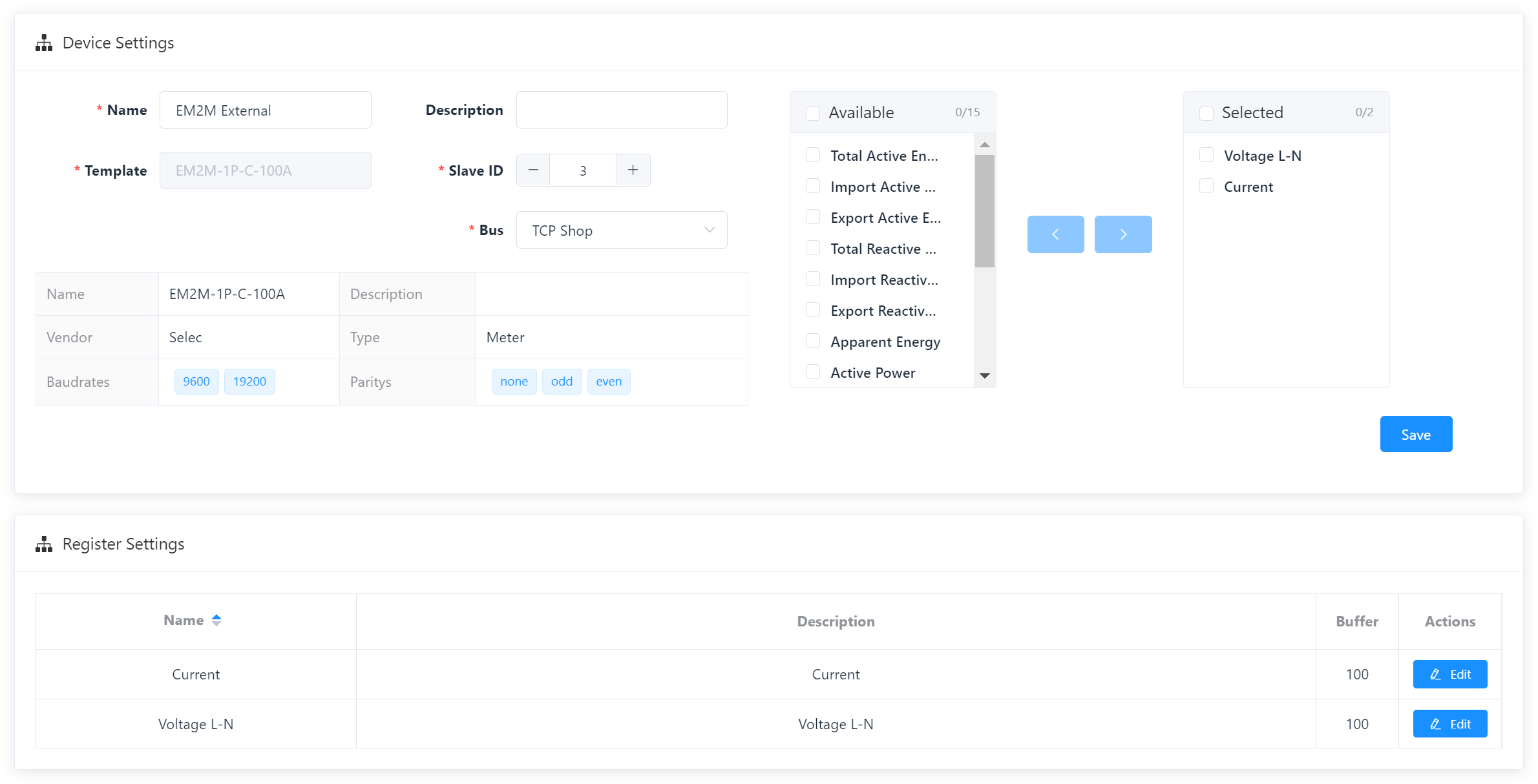
You can change the name, description, and buffer size of the Register afterward at any time by clicking on Edit.
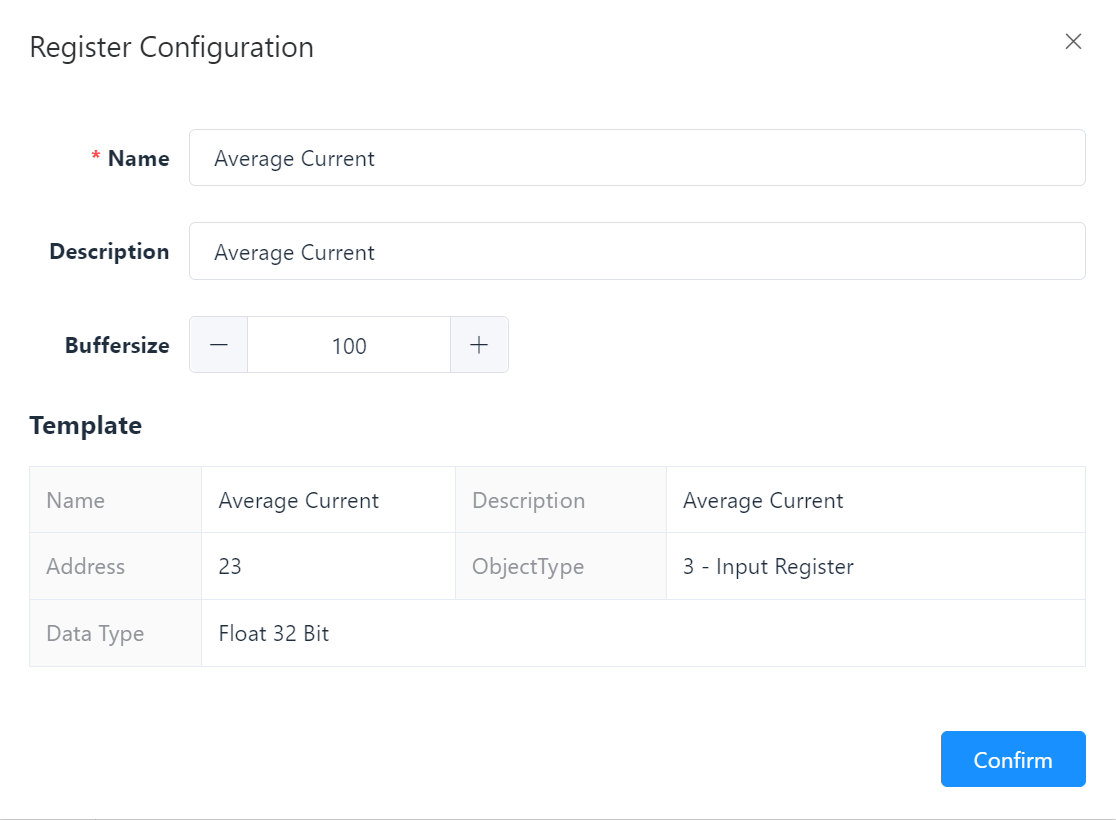
Edit Register - Settings
| Field | Description |
|---|---|
| Name * | This name was assigned when the template was created, but can be changed. |
| Description | A description may have already been added when the template was created. This can be edited. |
| Buffer size * | The buffer size follows a specific specification. This can be viewed in the dealer information. If necessary, it can be adjusted here. To do this, enter the value or change it by clicking +/- . |
| Template * | Displays the data from the corresponding device template. |
Note: All fields marked with * are mandatory.
Click on Confirm to secure the changes.