Function: System
System design with precision. This chapter explains the various options for monitoring, managing, and configuring the DO-1 operating system. For example, the status overview of the system, general settings, the option to create additional configurations, access to the system log, or network settings.
Overview
Status: Visual representation of internal processes
The current status and performance of the system can be tracked here in real-time. By regularly updating the data, you always receive up-to-date information about the performance of the system. All relevant system information can also be found here.
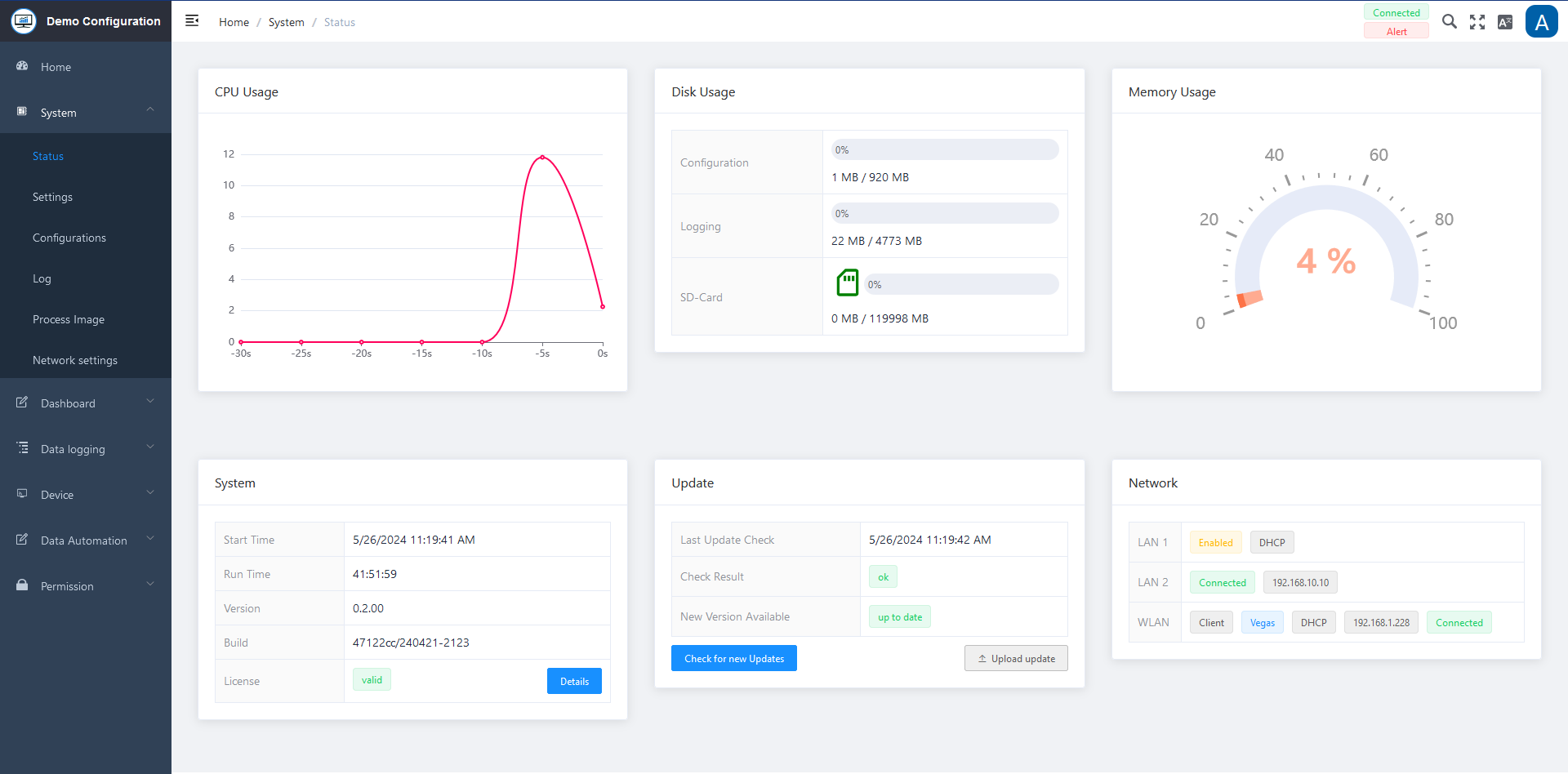
Status Overview
CPU Usage
Displays the current utilization of the central processing unit in a diagram.
Disk Usage
Displays the percentage of memory usage of the hard disk. Subdivided into:
- Configuration
- Logging
- SD card
Memory Usage
Displays the percentage utilization of the memory.
System
Contains all currently relevant system information:
- Start time
- Runtime
- Version
- Name of the setup
- Device ID
Updates
Displays the latest update information. You can search for new updates by clicking on the button.
Network
Displays the current network information; LAN and Port 2 information.
SD-Card Status
The SD card symbol shows the current status in different colors. Please see the table below.

| Color | Status Description |
|---|---|
| Grey | No SD card inserted |
| Orange | New SD card, but it needs to be formatted before it can be used. To do this, move the mouse over the icon and click to start formatting |
| Blue | Once formatting has been started, a blue symbol is displayed for the duration of formatting |
| Green | The SD card is ready for use. A bar indicates how much percentage of the card is used |
| Red | Error – Appears to be an error in the system, please contact the admin |
Settings: Storing e-mail and device information
The necessary information must be stored in the settings to enable the sending of e-mails for notifications from the system.
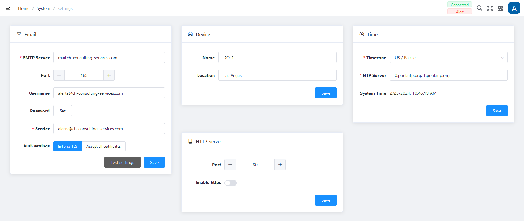
Email Specifications
| Field | Description |
|---|---|
| SMTP Server * | Enter the corresponding SMTP server ID; you can usually find the address of your SMTP email server in the Account or Settings area of your e-mail program; e.g. smtp.gmail.com |
| Port | Enter the corresponding SMTP port; Typical standard SMTP-Ports are 25 or 587 |
| User name | Enter the corresponding user name |
| Password | Enter the corresponding password for this user |
| Sender E-Mail * | Enter the sender e-mail address; e.g. john.doe@gmail.com |
| Auth. Settings | Select whether the encryption protocol (TLS) should be used and/or whether all certifications should be accepted when sending. Typical port for TLS use is 587. |
Note: All fields marked with * are mandatory.
The Test settings function can be used to check whether the entries can be executed successfully.
Device
| Field | Description |
|---|---|
| Name | Enter an individual device name |
| Location | Enter the exact location of the device; e.g. server room Göttingen |
Time
| Field | Description |
|---|---|
| Time zone | Select the time zone (drop-down) where the device is connected. |
| NTP Server | Already preset and is set automatically when the time zone is selected |
| System time | Displays the current date and time |
HTTP Server
| Field | Description |
|---|---|
| Port | Set the corresponding port via +/- or direct input. |
| Enable HTTPS | Activation via slider. It establishes a secure connection and encrypts data and passwords, making them inaccessible to other network users. |
Click on Save at the bottom of each input box to secure the entries.
Configurations: Creation and management of system configurations
This function offers the option of creating or importing additional configurations, i.e. different configurations can be created and selected and used for the same DO-1.
Some examples where this function is particularly useful:
- To control and monitor different machines
- When a test and a production environment are in use
- …
The basic version of the DO-1 contains the “Manual Demo” configuration.
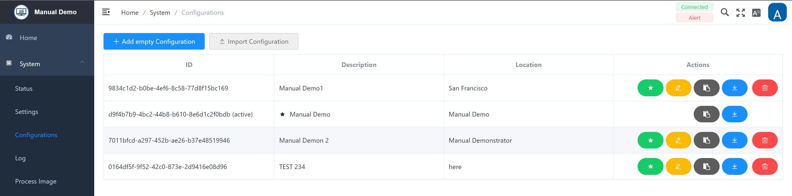
The ✓ in front of the name indicates the configuration currently in use. The only options for this configuration are Copy or Download.

Actions
| Action | Description |
|---|---|
| ▶️ | Configuration to be executed; if you want to display and use a different configuration, select it by clicking on the green button. |
| ✏️ | The created or imported configuration can be edited by clicking on the yellow button. This action is only available if the configuration is not the active configuration. |
| 📋 | This creates a copy of this configuration. Available for all configurations. |
| ⬇️ | Download the created configuration externally to your own computer. Available for all configurations. |
| 🗑️ | Deletion of the corresponding configuration. This action is only available if the configuration is not the active configuration. |
IMPORTANT: Please note urgently when changing to a different configuration:
- User and password settings may have changed.
- Network settings may have changed, which affects the IP address of the DO-1 and may need to be redetermined.
- If the Device Finder is used: Restart the Device Finder and/or press “Search” again to determine the current IP address.
Warning pop-up window:
If you switch to a different configuration, the following warning is displayed:
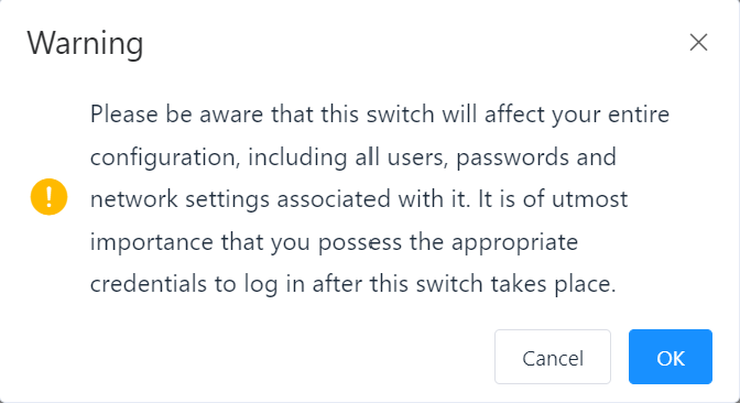
To make the change, this message must be confirmed by clicking OK.
Click on Cancel to retain the current configuration.
Add Configuration
Clicking on Add empty configuration opens a window with the following entry mask.
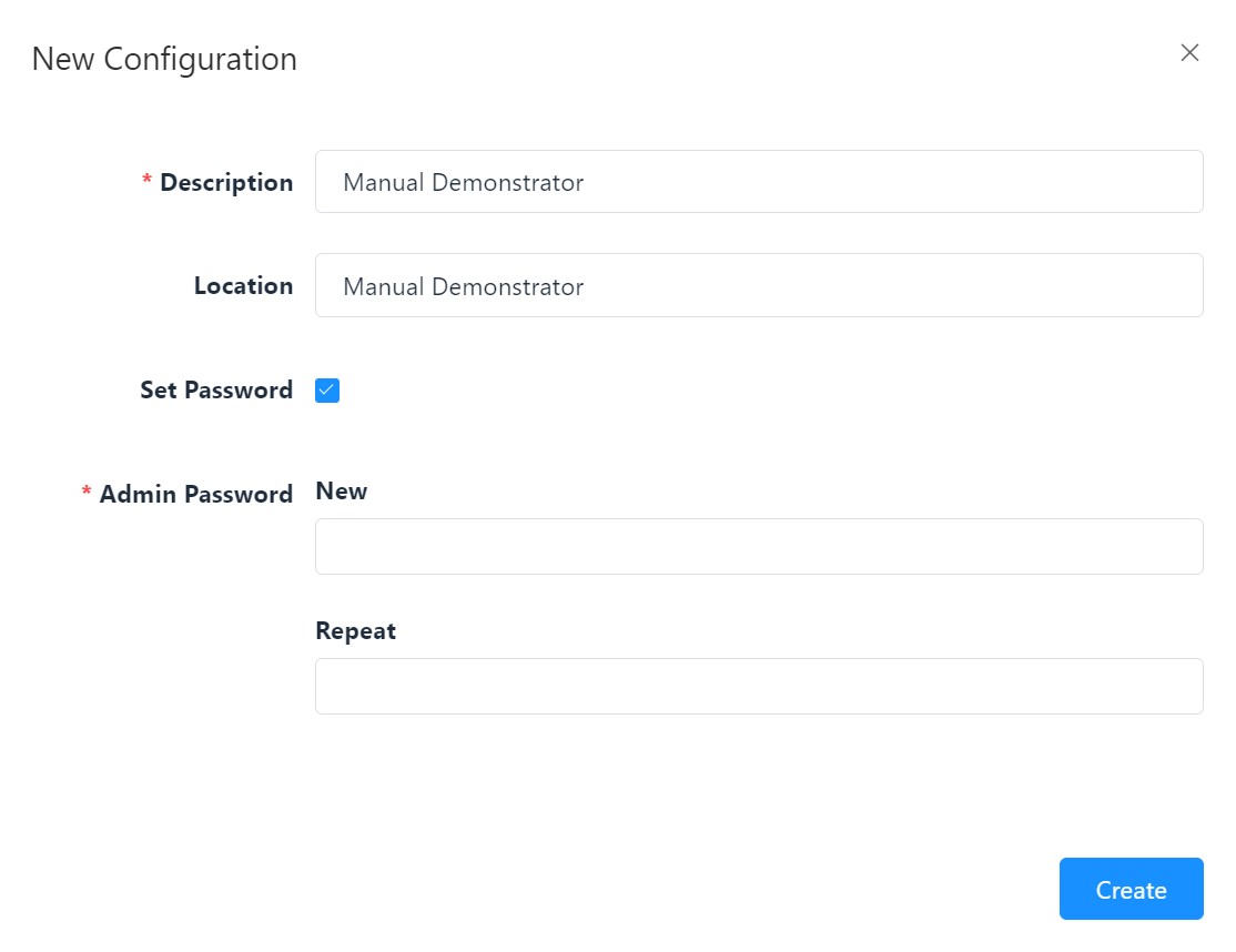
New configuration - Settings
| Field | Description |
|---|---|
| Description * | Individual entry, is used for later identification in the selection list |
| Location | Individual entry, optional, can be helpful for your own overview |
| Set Password | If the checkbox is ticked, two additional fields are displayed that require a password to be entered. The entries in these two fields must be identical! |
| Admin Password New * | Input field for the password, no password rules prescribed |
| Repeat * | For security reasons, the password must be entered again here |
Note: All fields marked with * are mandatory.
By clicking on Create, the new configuration is created and is available for selection and editing in the listing.
System Log: Recorded information on programs and system functions
System log: Recorded messages about programs and system functions. The system log records all events and activities of the DO-1. This includes error messages, warnings, user activities and other relevant information. The information it contains supports troubleshooting, security monitoring and the optimization of resource usage.
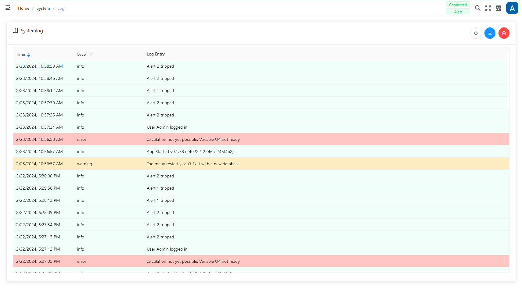
The following functions are available for the system log:
| Function | Description |
|---|---|
| Reload | Updates the log |
| Download | To save the entire system log in a file locally on the computer |
| Delete | Deletes the entire current system log. (A warning message must be confirmed) |
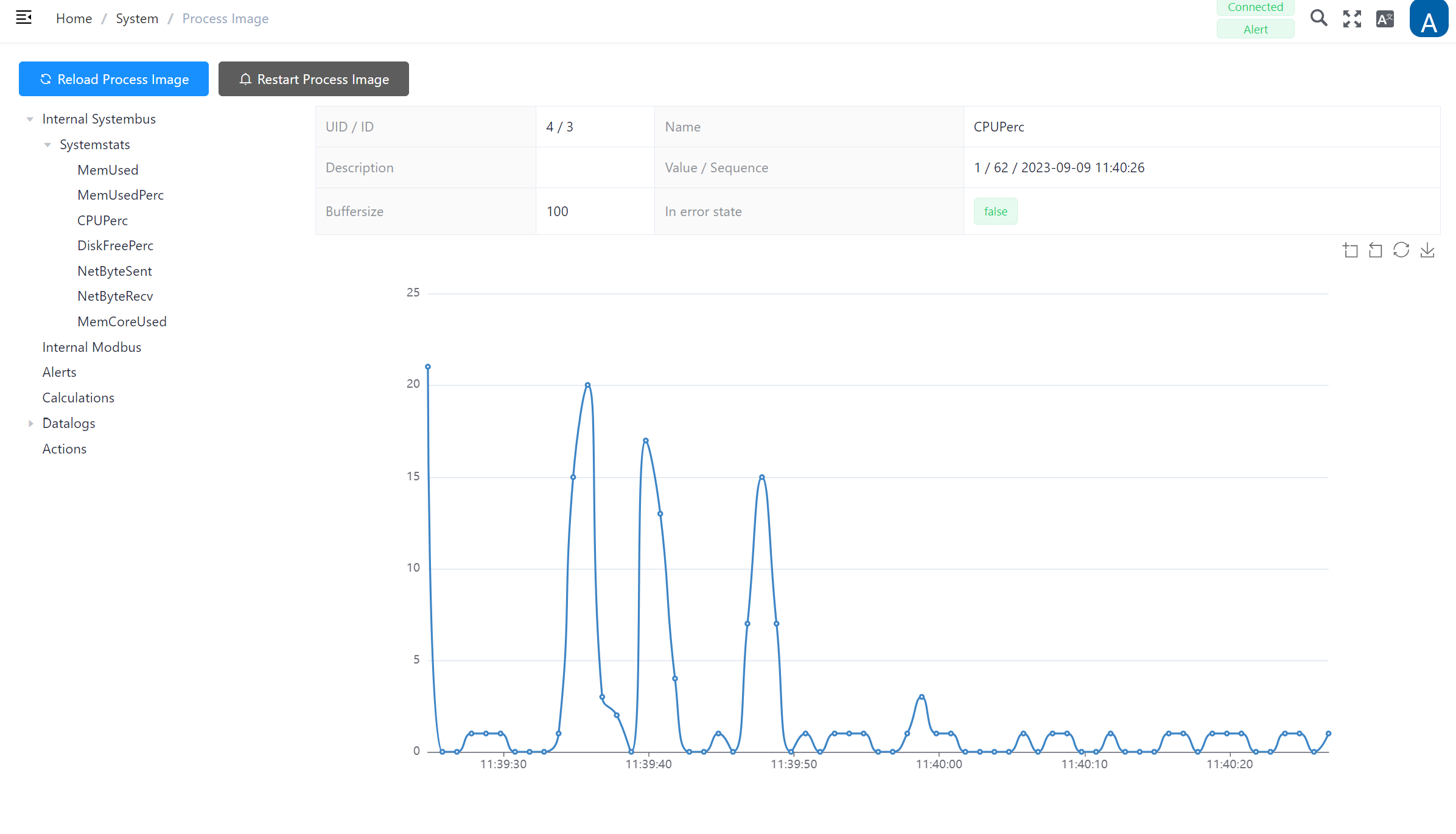
Process Image: Operational monitoring and control
On this page you can view all active processes of the DO-1. Process maps are critical for operators, engineers and control systems to effectively monitor and manage devices as they provide real-time insight into the device’s behavior and performance. This information is valuable for maintaining operational efficiency, diagnosing problems and making informed decisions regarding the operation of the device.
The integrated menu at the top left contains the selection of the main functions with the corresponding sub-processes. These are supplemented by further entries in the respective areas with additional views such as alarms, calculations and measures.
Internal menu:
- Internal System Bus
- System Stats (detailed views of: memory usage and capacities, CPU usage, NetByte information)
- Internal Modbus
- Alerts
- Calculation
- Data Logging
- Actions
Example CPUPerc (CPU usage):
Additional Functions
-
Selecting ‘Reload Process Image’ synchs the browser to the backend.
-
Select ‘Restart Process Image’ to stop and restart all internal processes. This may be necessary if a new device has been added to the DO-1 but does not yet appear in the overview.
-
The toolbar on the right-hand side offers additional functions for each process screen view. If you move the mouse pointer over the icons, the respective description is displayed.

(From left to right):
- Enables the current view to be enlarged in detail.
- Resets the last magnification.
- Resets the diagram to the original state and rebinds the data.
- Downloads a snapshot of the diagram as a png image.
Network Settings - Configuration and Administration
The information required to configure and manage the device’s network connections is stored in the network settings. The following important parameters can be configured and customized here:
- Default gateway
- DNS server
- LAN (Ports 1, 2)
- Wireless LAN (WLAN)
Default Gateway
Select which Gateway is to be set as default.
DNS Server
Enter the DNS server addresses; several entries are possible, by clicking on [+] another field appears, [trash bin] deletes an entry.
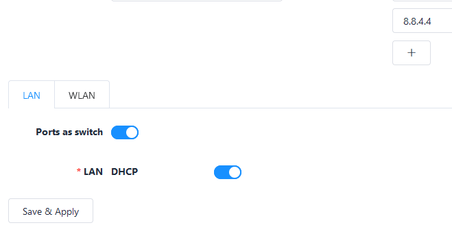
LAN Tab
Ports as Switch
Enable/disable via slider function.
If enabled refer to LAN DHCP settings.
LAN DHCP
Enable/disable via slider function; If DHCP is enabled: based on the client-server principle, it ensures that connection-seeking devices automatically obtain a reusable network address and all other relevant parameters. Always check the Default Gateway and DNS servers settings.
If LAN DHCP is not enabled; all necessary information (IP-Address, subnet mask, default gateway) needs to be entered manually.
If Ports as switch is not enabled; You can proceed with LAN 1 and LAN 2 as follows:
LAN1
Enable/disable via slider function; DHCP is used per default. Always check the Default Gateway and DNS Server settings.
Additionally, the Dynamic Host Configuration Protocol (DHCP) can also be disabled, via slider function. Then all necessary information (IP-Address, subnet mask, default gateway) must be entered manually.
LAN2
Enable/disable via slider function; DHCP is disabled per default. All necessary information (IP-Address, subnet mask, default gateway) must be entered manually.
Additionally, the Dynamic Host Configuration Protocol (DHCP) can also be enabled via slider function. Always check the Default Gateway and DNS Server settings.
WLAN Tab
This function is only available if the corresponding license is obtained!
WLAN enabled
Enable/disable via slider function; If WLAN function is enabled; you can choose between Access Point or Client:
Access Point (set per default)
- SSID *: Enter a SSID name (DO-1 per default)
- Password: Click on Set to assign a password and proceed with a corresponding entry.
- ID-Address: Default setting: IP 192.168.12.10
- Subnet Mask: Default setting: 255.255.255.0
- DHCP-Server: Enable/disable via slider function. If enabled; Determine the range for the IP address to be detected.
Client
- SSID *: Select the corresponding SSID
- Password: Click on Set to assign a password
- DHCP: Enable/disable via slider function.; DHCP is used per default. Always check the Default Gateway and DNS Server settings.
If not enabled; IP-Address and default gateway need to be entered manually.
Click on Save & Apply to secure the entries.
Note: All fields marked with * are mandatory!