Quick Start
This section is a practical guide that provides efficient solutions to frequently asked questions and problems. Regardless of whether you are a beginner or an experienced user, this guide provides simple help to quickly solve minor problems and improve understanding. The purpose here is to provide the knowledge needed to quickly identify and solve problems with clear instructions.
Quick Start Instructions
Package Contents
- 1x DO-1 Universal Monitor
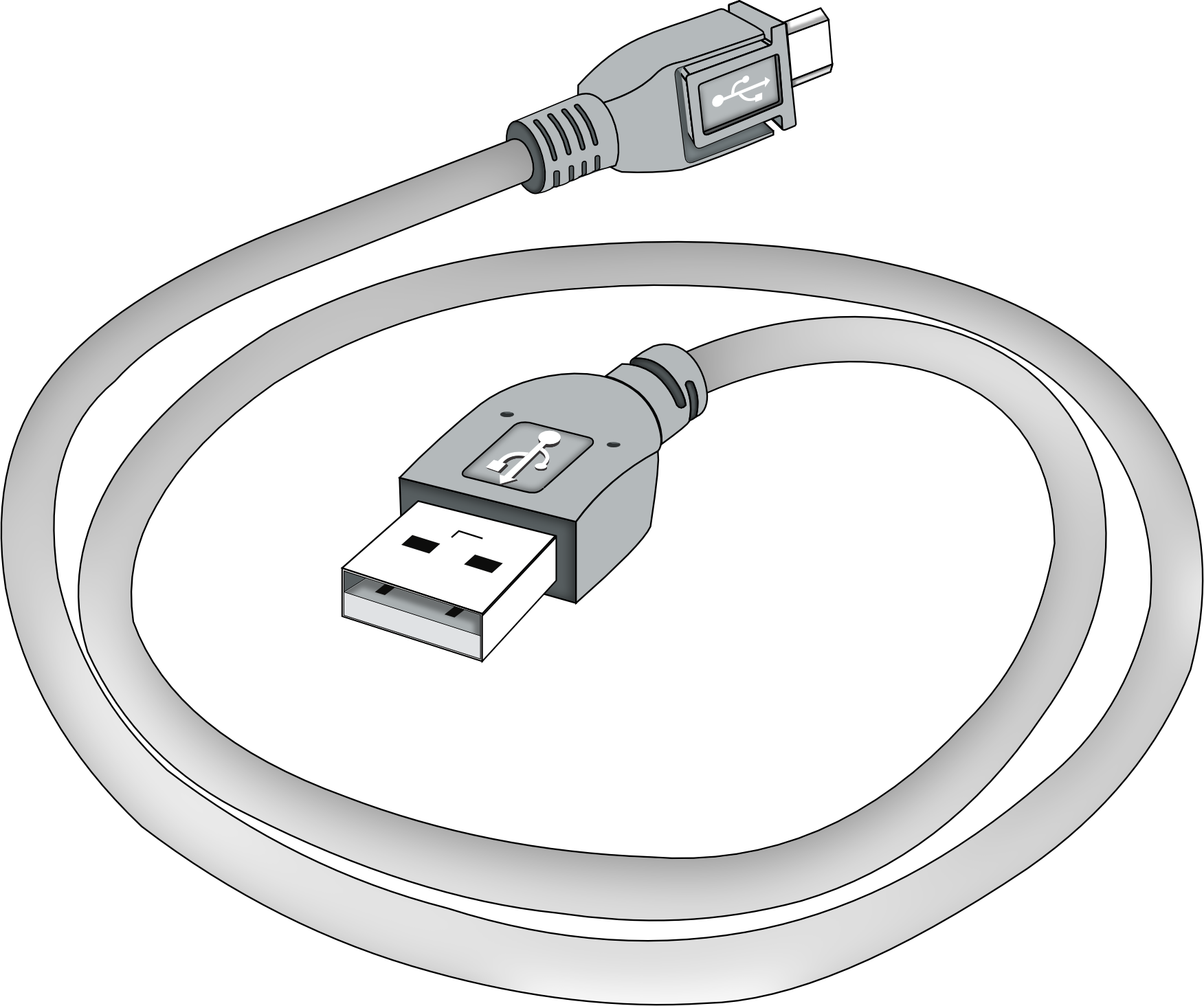
- 1x USB 2.0 Type-A / USB 2.0 Micro-B Cable
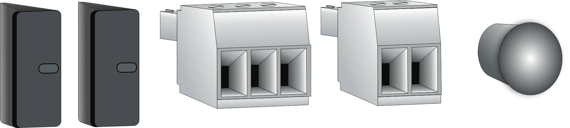
- 1x Antenna dust cap
- 2x USB Type-A dust caps
- 1x 2-pole connector with screw terminals
- 1x 3-pole connector with screw terminals
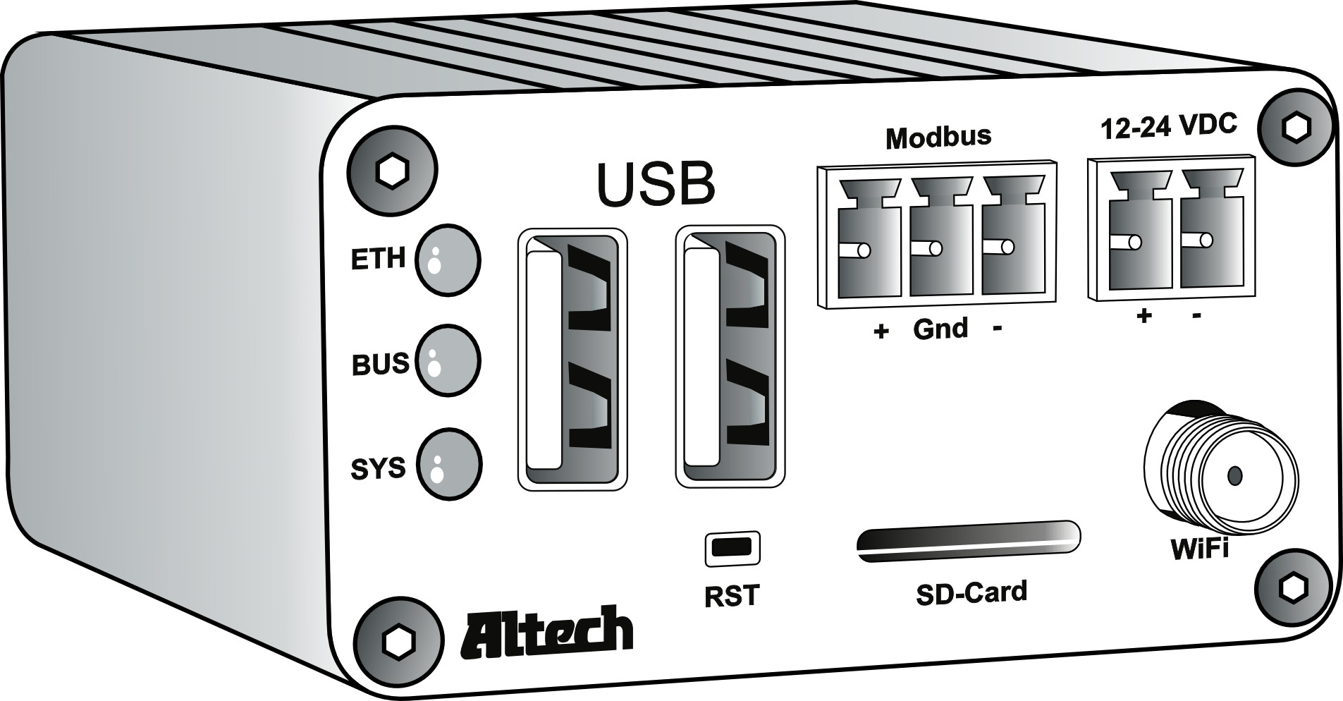
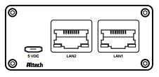
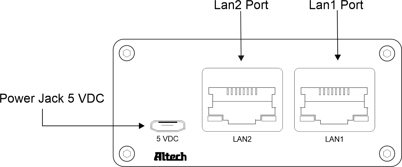
Front and Back View of DO-1
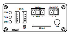
Connectors and Indicators on the DO-1
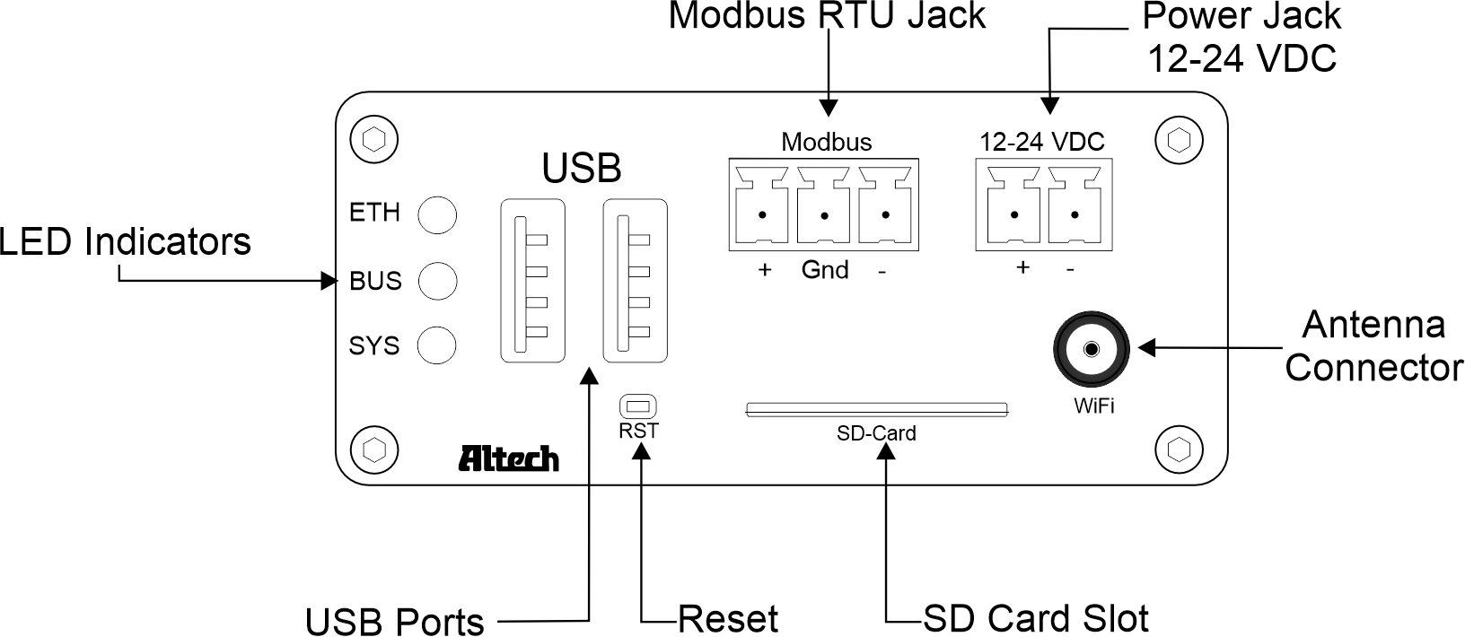
- LED ETH: Lights up green when the connection to the Ethernet network is established.
- LED BUS: Flashes green in time with the bus cycle time of the internal Modbus.
- LED SYS: Flashes red when the DO-1 is in operation.
- USB: USB ports are provided for future use.
- Modbus RTU Jack: Connection of the Modbus RTU devices to the internal Modbus of the DO-1.
- 12-24V DC Power Jack: Main power supply of the DO-1, 12-28V DC voltage.
- Antenna Connector: WiFi antenna connection possibility provided for later use.
- SD Card Slot: SD card slot for SD cards up to 128 GB.
- Reset: Causes a software restart after an operation of 5 seconds.
- Power Jack 5V DC: Auxiliary power supply 5V DC voltage.
- LAN1 Port: Ethernet network connection 1.
- LAN2 Port: Ethernet network connection 2.
Setup and Installation
In order to use the functions of the DO-1 properly, the universal monitor must be connected correctly. The DO-1 is then operated via a web-based user interface.
Basic connections for the initial setup:
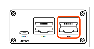
- Connection of the network cable to the port ‘LAN1’.
- Connect the 2-wire RS485 cable using the 3-pole connector plug. Ensure correct polarity, ground A (+) and B (-) as well as the shield of the cable.
- Connecting the power supply 12-24V DC by means of the 2-pole connector plug. Here also pay attention to correct polarity, (+) and (-).
- After connecting the power supply, the
SYSLED first flashes for approx. 15 seconds, then theETHLED should light up green.
Accessing the DO-1 Configuration Interface
The DO-1 configuration interface can be accessed via
DHCP
or
static IP
address assignment. By default, LAN1 is set up as a DHCP client, while LAN2 is assigned the static IP address 192.168.10.10.
- Connect an Ethernet cable from LAN1 on the DO-1 to a LAN segment in which a DHCP server is available.
- Use our DO-1 Device Finder to locate the current IP address of the DO-1. Please read DO-1 Device Finder and follow the described steps.
- Connect an Ethernet cable from the Ethernet port on your computer to the port on the DO-1 labeled LAN2.
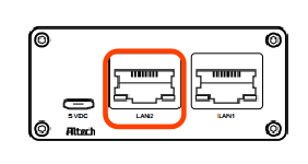
- Make sure that your Ethernet adapter is on the same network as the DO-1 (192.168.10.X); if you’re not sure, you can set it to
192.168.10.2/ subnet mask255.255.255.0, for example. - Launch your web browser. Type
http://192.168.10.10in the address field and press Enter (PC) or Return (Mac). The login screen appears.
DO-1 Configuration
The web-based user interface can now be used to set up the DO-1. See below the recommended step-by-step sequence [with chapter assignment in the user’s manual]:
-
a) Connect the computer to the same network as the DO-1. b) Make sure that the DO-1 is started properly (see Connecting the DO-1). c) Open a web browser on the computer and enter the IP address of the DO-1 in the command line, e.g.,
http://100.75.199.12/. d) The web portal login page should be displayed.The default administrator login credentials are:
- Username:
admin - Password:
admin
- Username:
Further recommended steps:
- Network Settings
- Check for Software Updates
- Email and Device Configuration
- Modbus RTU and TCP Settings
- Creation of the device templates of the connected Modbus devices
- Connection of the respective Modbus devices to the Modbus RTU or to newly created Modbus TCP
- Calculations Setup (if necessary)
- Alert Setup
- Action Setup
- Configuration of Data Logs (if necessary)
- Creation of the visualized overview (dashboard) of measured values of the connected devices, as well as created alarm functions
- User and role assignment settings
Restart and Reset to Default Values
The LEDs, i.e., indicator lights, serve as visual indicators for the various phases and times. Holding the reset button allows you to initiate the desired change.
-
Restart
- Press and hold the reset button.
- All LEDs go out except for the
power LED, which remains on continuously. - Once the
BUS LEDlights up again, release the reset button. - The device then restarts.
-
Reset Values (Default Status)
- Proceed as with the restart of the device, but continue to hold down the reset button.
- Once the
ETH LEDalso lights up additionally, release the reset button. - This resets all values, and a new configuration file is created.
Troubleshooting and Problem Solving
Communication Problems with RS485
Communication errors in a Modbus RS485 network can be caused by various factors. In general, most RS485 problems can be divided into two main areas:
-
Problems with Physical Wire Connections
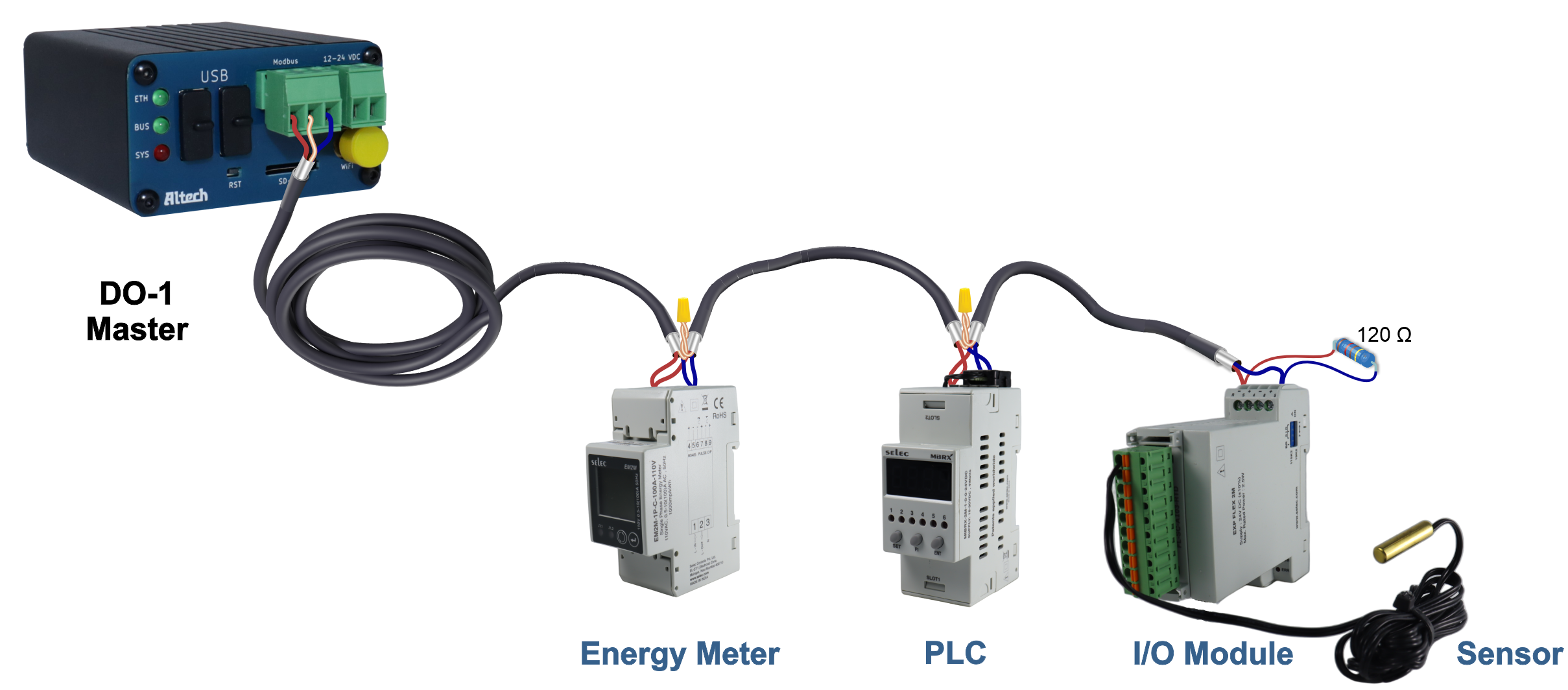
Physical connections are critical for RS485 communication. RS485 devices require a suitable interface, such as screw terminals, DB9, or RJ-45 connectors. Important pin assignments are +, -, and ground (sometimes referred to as A, B, or Tx/Rx+, Tx/Rx-, and ground). RS485 devices are often connected in a daisy chain configuration.
If the network is configured in this way and communication problems or unreliable communication occur, it is essential to perform the following diagnostic tests:
-
Verification of Physical Connections
First, check that all connections are tight and properly fastened. Loose wire connections can cause intermittent communication problems in an RS485 network. -
Test the RS485 Ports
A device in the network could have a faulty RS485 port. To check this, the RS485 devices should be replaced one by one with working devices, especially in multi-drop RS485 configurations. A faulty serial port on one device can affect communication for all others on the same cable. -
Eliminate Electrical Faults
Although RS485 is known for its resistance to electrical interference, the proximity of communication cables to machines or equipment that generate significant electrical interference can be problematic. In such cases, it is advisable to reroute the cables to minimize exposure to the sources of interference. -
Minimize Ground Loops
Ground loops can negatively affect the signal integrity of RS485 when multiple devices on the RS485 cable connect the shield to ground. This interference can disrupt the RS485 signal. To prevent interference, the cable shield should be grounded at one end only and accidental grounding in the middle of the cable should be avoided. -
Consider Termination and Impedance Matching
A terminating resistor, also known as a termination resistor, is used in RS485 communication systems at the end of the line to ensure signal integrity and reliability. RS485 is a serial communication interface for industrial applications over long distances. It is used to prevent reflections, impedance matching, noise immunity, and to extend the communication range. The exact resistance value may vary, but in most cases, it is 120 Ohm to match the line impedance.
ℹ️The terminating resistor is normally only connected to the ends of the RS485 line and not to each device. If you have multiple devices in an RS485 communication chain, you should only use the terminating resistor at the ends of the line, not at each device in between.⚠️DO-1 only requires one terminating resistor at the end of the line as it already has an integrated 120 Ohm terminating resistor. -
-
Mismatched Communication Settings
Common RS485 problems are caused by communication settings that do not match. After confirming the physical connections, you should check the communication settings of all devices on the network. These communication settings mainly include the RS485 port configurations on each device.
Data parameters such as:
must be identical for each device on the communication cable.